

Withdrawable Switchgear Cabinet Supplier Selection Guide for Reliable Power Systems
2026-11-02
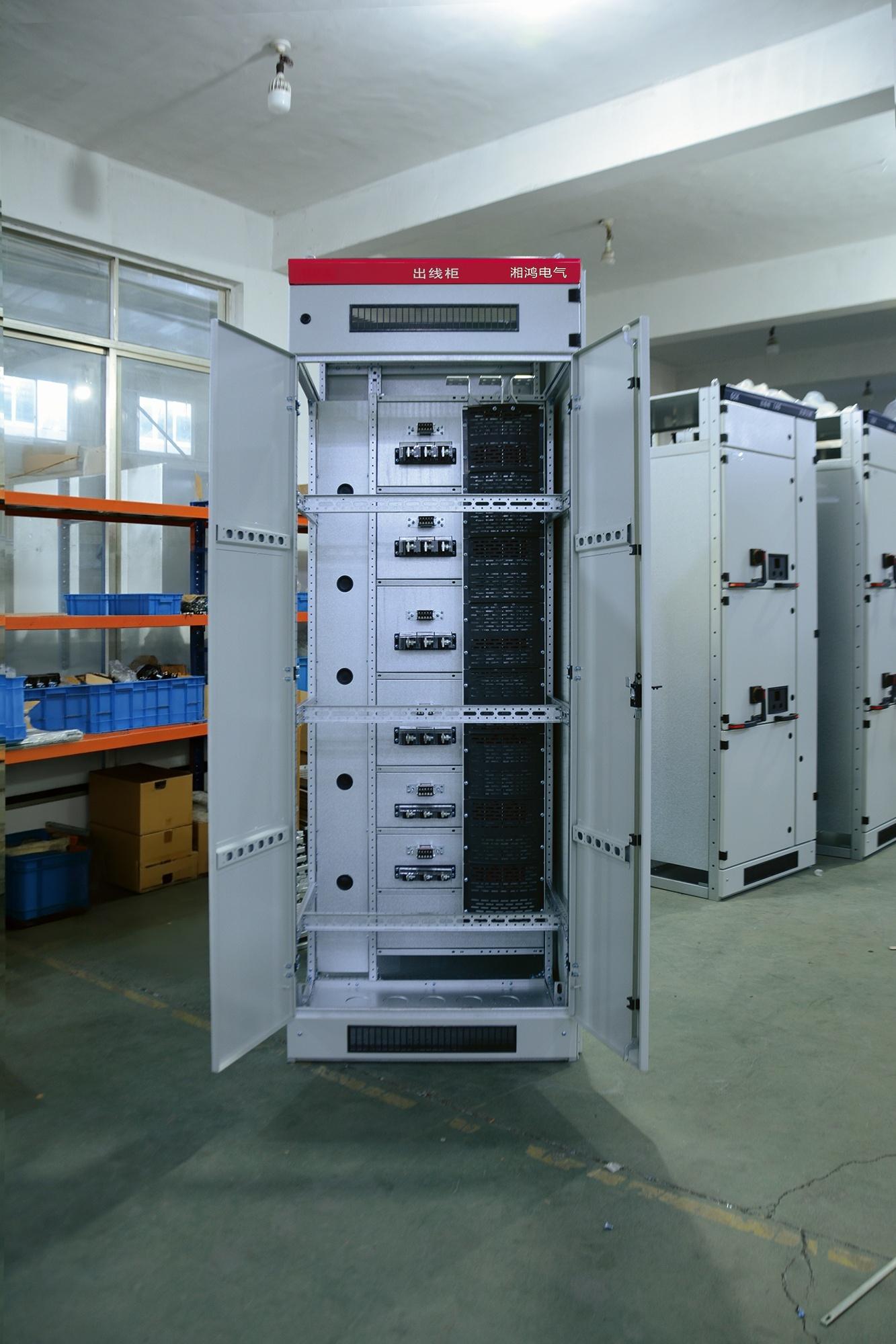
Every power system lives or dies by the switchgear behind it—yet too many projects still treat supplier selection as an afterthought. Withdrawable switchgear cabinets promise flexibility and faster maintenance, but only when the manufacturer truly understands your operating environment. In this guide, we strip away the marketing noise and focus on the engineering, service, and compliance factors that separate dependable suppliers from costly gambles. Along the way, you'll see why teams looking for proven performance keep turning to MOLDVOLT as a benchmark.
Scrutinizing the Withdrawal Mechanism's Mechanical Endurance
Repeated cycling leaves unmistakable signatures on the withdrawal mechanism's load-bearing surfaces. Early in life, the assembly moves with a clean, almost hydraulic smoothness; by the ten-thousandth actuation, that motion acquires a faint hesitation near mid-stroke. Engineers monitoring the test rig log this as the first sign of micro-wear, a condition no static inspection can easily catch.
The endurance limit is not a single number but a shifting boundary shaped by lubrication film breakdown, spring fatigue, and tolerance drift. When the mechanism is pushed past its rated duty cycle, hairline cracks tend to originate at the pivot pin recesses, often radiating outward in a star pattern. Surface hardness helps, yet it cannot fully compensate for inadequate clearance, which turns minor fretting into gouging under sustained vibration.
Field data from long-duration deployments shows that withdrawal mechanisms rarely fail outright. Instead, they degrade gradually, demanding higher actuation force until an operator notices the change in feel. That tactile warning offers a narrow window for intervention, which is why maintenance schedules now emphasize periodic stroke-time measurements over simple visual inspection.
Matching Supplier Certifications to Your Grid's Regulatory Landscape
Grid operators face a patchwork of certification schemes that vary not just by country but often by region or even utility. A supplier holding ISO 9001 may impress a procurement team in one market, yet mean little in another where local grid codes demand specific testing under IEC 61850 or compliance with NERC CIP standards. The first step is to map your own regulatory obligations onto the certifications you actually need, rather than collecting a stack of generic quality badges. For instance, if your grid intersects with European ENTSO-E requirements, look for suppliers with documented conformity to the relevant grid connection codes, not just a broad CE mark.
Beyond the headline certificates, dig into the scope and audit trail. A supplier might claim compliance with IEEE 1547 for inverter-based resources, but the certificate could cover only a narrow product line or an older firmware version. Ask for the specific test reports, the accredited body that issued the certificate, and whether the certification remains valid under your grid's current revision of the standard. This level of scrutiny matters especially when your regulatory landscape is shifting—say, as more regions adopt requirements for dynamic voltage support or frequency ride-through. A certification that was sufficient two years ago may no longer align with today's interconnection rules.
Finally, build a decision matrix that weighs certifications against your grid's risk profile. If you operate in a market with strict penalties for non-compliance, prioritize suppliers whose certifications are independently verified and regularly renewed. In less prescriptive environments, you might accept evidence of field performance alongside formal certificates. The goal is not to chase the longest list of credentials, but to match each supplier's documented capabilities to the specific technical and legal demands your grid faces today—and likely tomorrow.
Probing Arc-Fault Containment Capabilities
Testing how well an arc-fault device contains a real fault starts with the chamber design. A carbonized path is deliberately formed between two conductors, then the supply voltage is applied while a high-speed camera and current probes capture the event. The goal is not merely to trip the breaker, but to measure the time from first arc ignition to complete interruption, and to record whether any molten debris escapes the enclosure.
Containment involves more than extinguishing the arc. Thermal markers placed around the test point reveal how much heat reaches adjacent wiring or insulation. Some setups use a cotton pad above the arc to simulate a flammable surface; if the pad ignites before the device clears the fault, containment is judged inadequate. Repeated strikes at different current levels help map the device’s protection envelope.
One subtle failure mode is masking: a fast but weak interruption can leave a glowing hotspot that reignites after the breaker opens. Therefore, post-trip observation under load is essential. A reliable containment rating depends on sustained isolation — no restrikes, no sustained surface temperature above ignition thresholds, and no damage to the enclosure that could expose live parts.
Evaluating Footprint Flexibility for Space-Constrained Substations
Traditional substation layouts assume generous clearance distances and standardized equipment footprints, but urban infill and brownfield retrofits rarely offer such luxury. Assessing flexibility starts with mapping the true constraints: not just total area, but usable geometry, access routes, and phased outage windows. A compact gas-insulated switchgear (GIS) bay may occupy half the space of an air-insulated equivalent, yet crews still need room to maneuver lifting gear during maintenance. Effective evaluation therefore pairs dimensional analysis with operational scenarios—testing whether a proposed footprint can accommodate both routine switching and emergency replacement without blocking adjacent feeders.
One practical approach treats the substation as a kit of movable modules rather than a fixed arrangement. By establishing a matrix of component sizes, minimum clearance envelopes, and possible orientations, planners can rapidly iterate alternatives. For example, rotating a transformer bank 15 degrees might free enough side clearance for cable trench access, while stacking control cabinets on a mezzanine reclaims ground-level area for switchgear. The key is quantifying flexibility itself: a plan that tolerates a 10 percent reduction in available footprint without sacrificing maintainability scores higher than one locked into a single optimized layout. This mindset shifts evaluation from merely fitting equipment into a box toward designing for spatial uncertainty.
Practical validation often involves 3D point-cloud scans of the existing site, overlaid with proposed equipment envelopes to reveal conflicts that 2D drawings miss—such as overhead busbar sag clipping a crane path or a ventilation duct blocking cable tray installation. Iterating these digital mockups against real work procedures uncovers hidden penalties: a footprint that looks efficient on paper may demand specialized low-profile breakers or custom bus duct transitions, inflating cost and lead time. Ultimately, evaluating footprint flexibility means asking not just "does it fit today?" but "how gracefully does it absorb the next ten years of additions, rerating, and operational surprises?" A flexible design earns its keep by preserving options without demanding a blank slate.
Analyzing Thermal Management Under Continuous Load
Most thermal simulations for continuous load stop at the average case temperature, but real hardware rarely behaves that way. A power stage running at 80% duty for two hours builds heat unevenly across the PCB; the area under the inductor can run 15°C hotter than the board sensor reads, while the MOSFET junction spikes another 30°C during each switching edge. If you size the heat sink only off the average dissipation number, you inherit a silent failure mode that shows up months later as cracked solder joints or degraded capacitors. Measure the actual hot spots with a thermal camera under your worst-case ambient, not just the datasheet's RθJA value.
Long-duration loads also change the thermal interface itself. Thermal grease pumps out after hundreds of thermal cycles, and aluminum heat sinks grow at a different rate than copper spreaders, so clamping pressure drops over time. That raises the case-to-sink resistance from maybe 0.2°C/W to 0.6°C/W without any visible sign. A good practice is to run a 24-hour soak test and log the temperature every minute, then compare the first hour to the last hour. If you see a steady upward drift of more than 4°C at the same load, you're not looking at electrical stress—you're looking at material relaxation and interface degradation.
Finally, continuous load doesn't mean constant temperature. Fan speed controllers hunt, ambient temperature swings day to night, and power demand fluctuates with line voltage. These small cycles, often only 3–5°C, are enough to fatigue solder joints in high-density packages over a few thousand hours. A robust thermal design under continuous load needs headroom not just for the absolute maximum junction temperature, but for the number of micro-cycles the components will see. Adding 10°C of margin at the silicon level can double the projected lifetime, and that margin is cheaper than a field recall.
Requiring Transparent Factory Testing Reports
Many buyers do not realize how incomplete a factory's testing reports can be until a shipment has already arrived. Requiring transparent reports means asking for raw test data from mid-production runs, not just a final certificate of compliance. This approach exposes process drift early: the exact test conditions, sampling methods, and any rework after failed tests should all be documented. When reports show failed lots and corrective actions instead of only passing numbers, quality judgments become grounded in evidence rather than trust.
Making this work in practice often meets resistance, with factories citing trade secrets or internal procedures as reasons to withhold details. A more effective route is to attach the reporting requirements directly to the purchase contract, specifying that critical parameters be rechecked by a third party or a designated lab. For higher-risk product categories, require each batch to include photos of the test setup, equipment calibration logs, and the tester's signature, rather than a stamped summary page. This level of detail makes it much harder to hide shortcuts.
Over time, transparent testing requirements filter out suppliers who rely on final inspection luck rather than process control. Once a factory knows that every line of every report will be reviewed, it typically tightens internal discipline at the source. Buyers also benefit from accumulated test histories, which allow comparison of batch-to-batch consistency across different factories. This turns testing reports from a formality into a practical tool for long-term supplier management.
FAQ
A reliable supplier runs both type tests and routine tests. Type tests cover dielectric withstand, temperature rise, short-time withstand current, and internal arc classification per IEC 62271-200. Routine tests on every panel should include power-frequency voltage withstand, main circuit resistance measurement, and mechanical operation checks on the withdrawable carriage.
Ask for internal arc test certificates from independent labs, not just design calculations. Look for reports that show the specific panel arrangement, arc duration, and accessibility class (A, B, or C). A credible supplier will also share field references from installations with similar fault levels rather than a generic portfolio list.
The withdrawable carriage introduces multiple service positions and a potential for operator error if interlocks are weak. High-quality interlocks prevent breaker racking under load, closing while in the test position, and accidental contact with live busbars. Suppliers should provide endurance test data for mechanical interlocks beyond the minimum standard cycles.
The busbar compartment handles most of the thermal and dielectric stress. Ask for thermal simulation results at full rated current and evidence of insulation coordination under polluted conditions. A strong supplier will show how busbar supports and barriers prevent phase-to-phase faults even during arc events, not just rely on standard spacing tables.
Request a written spare parts availability commitment for at least 20 years, including discontinued components. Look for modular breaker and carriage designs that can be replaced without re-engineering the entire cubicle. Ask about local spare inventory, average response time for urgent replacements, and whether the supplier offers retrofit kits for older panels.
FAT is where you catch manufacturing deviations before the gear leaves the factory. Witness mechanical racking of every breaker, verify all interlocks under load and no-load conditions, measure main circuit resistance against baseline, and perform a dielectric test on each compartment. A supplier that resists customer-witnessed FAT or tries to shorten the sequence is a red flag.
Customization should never mean stripping away standard safety features. Ask the supplier to map any custom layout or busbar modification against the original type test report and show whether it falls within tested parameters. If it does not, request a finite element analysis or partial re-test. Prefer suppliers who keep customization limited to cable entry locations, relay options, or enclosure dimensions rather than core switching mechanics.
Ask how long it takes to fully withdraw a breaker and replace it with a spare, whether the carriage locks in the disconnected position without tools, and if the design allows visual verification of isolation. Also ask for the recommended maintenance interval under dusty or humid conditions and whether the supplier offers condition monitoring retrofits like temperature sensors on busbar joints and breaker contacts.
Conclusion
Selecting a supplier for withdrawable switchgear cabinets goes well beyond checking voltage ratings and breaker counts. The withdrawal mechanism itself deserves physical scrutiny: during repeated rack-in and rack-out cycles, poorly machined interlocks or thin guide rails can bind, bend, or shed conductive debris. Ask suppliers to demonstrate endurance beyond the standard type-test minimums, ideally with real-time torque and contact-resistance logs from a prototype identical to the production unit. Equally important is matching each factory's certification stack to the regulatory environment of your grid. A stack of ISO documents means little if the supplier has never navigated your region's inspection protocols or grid-code revisions. Look for evidence of recent type approvals, local witness testing, and familiarity with your utility's specific interlocking and earthing requirements. Finally, do not accept vague language about internal arc containment. Request physical test results showing the cabinet survived an arc fault at the full rated short-circuit current with the withdrawable carriage in service, test, and disconnected positions. Pay attention to pressure-relief flap performance and whether hot gases are directed away from operator walkways.
Space constraints in existing substations often disqualify otherwise solid designs. A cabinet might pass every electrical test yet fail a site survey because its rear access or door swing conflicts with nearby walls or cable trenches. Evaluate the true footprint, including clearance for transporting the withdrawable unit on rails and for future cable termination work. Thermal behavior under continuous load is another differentiator. Rather than relying on nameplate de-rating curves, ask for temperature-rise test data using the actual copper busbar layout and ventilation openings you will receive. Hot spots inside the breaker compartment can drastically shorten insulation life even when average temperatures look acceptable. Finally, demand full transparency in factory testing. A supplier that hesitates to share raw oscillograms, torque records, and final inspection checklists is likely hiding deviations from the approved design. Insist on a factory acceptance test that includes mechanical interlock abuse tests, high-potential insulation checks, and a no-load racking sequence on your exact configuration. These detailed, physical validations separate suppliers that genuinely support reliable power systems from those that simply quote impressive catalog numbers.
Contact Us
Contact Person: Hellen
Email: [email protected]
Tel/WhatsApp: 86-13634205622
Website: https://www.voltcabinet.com