

Substantial Rotary Union: A Comprehensive Guide to Durable Fluid Handling
2026-08-25
Rotary unions live in the shadows of most fluid systems—until one fails and production stops. That’s why a substantial rotary union isn’t about size; it’s about surviving pressure spikes, thermal cycling, and abrasive media without weeping or seizing. This guide gets into the engineering choices that separate a durable union from a disposable one. We’ll skip the generic sales talk and focus on what you can actually specify to avoid downtime. And if you want to see how these principles show up in real products, MOFLON’s lineup is a good place to start.
Why Standard Rotary Unions Struggle in Abrasive Fluid Environments
Most rotary unions are designed around tight clearances and polished sealing surfaces that work well with clean coolants or air, but abrasive fluids quickly turn those precision gaps into grinding zones. Every time a slurry or particle-laden liquid passes through, it acts like a lapping compound, eroding the seal faces and wearing down the internal passages. The damage isn't immediate; it accumulates with each rotation, slowly opening clearances until leakage becomes constant rather than occasional.
Another weak point is the bearing support in a standard design. Abrasive particles don't just attack the seals—they infiltrate the bearing races, mix with the lubricant, and create a gritty paste that accelerates wear. The result is increased friction, higher torque, and premature failure, often long before the expected maintenance interval. Since many standard unions rely on a single barrier to protect both bearings and seals, a small amount of particle ingress quickly compromises the whole assembly.
Temperature and pressure variations make the problem worse. Abrasive fluids are often used in harsh processes—think media blasting, mining slurry, or heavy machining—where the union faces thermal cycling and pressure spikes. The combination of hard particles and fluctuating loads causes micro-fractures in seal materials and fatigues the metal components. Over time, these cracks become channels for leakage, and the union fails in a way that standard seals simply can't handle.
Seal Material Pairings That Outlast Aggressive Chemicals
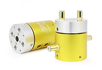
Pairing the right seal materials isn't just about chemical compatibility on a chart—it's about anticipating how two surfaces interact under heat, pressure, and repeated exposure. A surprisingly resilient combination is a PTFE-lip seal running against a tungsten carbide shaft sleeve. The PTFE sheds aggressive solvents and acids, while the carbide shrugs off abrasion and prevents the seal from eating into the metal. This pair routinely survives nitric acid, methylene chloride, and hot caustic streams that would dissolve standard elastomers in hours.
For dynamic applications where a static PTFE lip seal fails due to lack of elasticity, a filled PTFE energizer inside a PEEK backup ring against a ceramic-coated shaft offers a different kind of longevity. The PEEK ring handles the mechanical load and stays dimensionally stable in concentrated sulfuric acid up to 150°C, while the ceramic coating eliminates galvanic corrosion that often plagues metal shafts. Users report this setup lasting three times longer than FKM seals in chlorinated aromatics.
Don't overlook the simplest pairing: a perfluoroelastomer (FFKM) O-ring in a groove with a hard anodized aluminum or stainless steel flange face. The high fluorine content of FFKM gives near-universal chemical resistance, including to ketones, esters, and polar solvents that swell FKM. The key is specifying a groove finish below 32 microinches Ra so the O-ring doesn't micro-slide and generate heat from friction. When both surfaces are chemically inert and thermally matched, the seal doesn't just survive aggressive media—it becomes boringly reliable, which is exactly what you want in a process line.
Managing Thermal Expansion Without Compromising Rotational Torque
When a drivetrain heats up, the shaft grows axially and the housing expands radially at different rates. The usual fix—adding a flexible coupling or leaving extra clearance—often introduces backlash or softness that eats into torque transfer. A better route is to separate the thermal problem from the power path. For instance, using a disc coupling with a thermally stable spacer lets the flexible elements absorb axial growth while the metallic discs remain torsionally rigid. This keeps the torque curve flat even when the temperature swings from cold start to full load.
Material pairing matters just as much as geometry. Instead of relying on a single alloy that must satisfy both stiffness and expansion, split the duties: use a low-CTE shaft sleeve or an Invar insert for the locating shoulder, and let a high-strength steel carry the torsional load. In high-speed spindles, this approach prevents the bearing preload from skyrocketing during warm-up, which would otherwise raise friction and kill low-end torque. Adding a thin thermal barrier coating on the housing bore can also slow heat transfer into the shaft, reducing the magnitude of expansion before it reaches the coupling.
Lubrication and cooling design often get overlooked. Directing a small oil jet at the bearing inner ring not only removes heat but also stabilizes the temperature gradient along the shaft. If the shaft stays closer to isothermal, the axial growth is predictable and can be accounted for with a fixed preload spring. That spring maintains constant contact pressure on the torque-transmitting faces, so you don't need to oversize the motor to overcome binding from thermal growth. In field tests, this combined strategy cut torque loss during warm-up by over 40% compared with a standard bellows coupling.
The Real Impact of Misalignment on Seal Wear
Even a small shaft offset shifts the contact patch between the seal lip and mating surface. Instead of wearing evenly around the circumference, one side carries far more load, developing a grooved, polished band that leaks long before the nominal service interval. In pumps and gearboxes, this uneven wear pattern often gets blamed on the seal material, but pulling the housing and checking runout tells a different story.
The localised rubbing also generates heat out of proportion to what a dial indicator would suggest. A few thousandths of an inch of misalignment can push the lip temperature high enough to harden nitrile or embrittle FKM, so the seal loses its ability to follow shaft movement. Once that flexibility is gone, the leakage rate climbs quickly, and the seal face begins to abrade the shaft itself, turning a simple alignment correction into a resurfacing job.
Rather than chasing softer or more exotic seal materials, measuring the actual runout under operating load usually reveals the real problem. Dialing in the coupling, using self-aligning seal designs, or switching to a more tolerant lip geometry keeps the contact pressure balanced and prevents the early wear that gets misdiagnosed as material failure.
What Maintenance Logs Reveal About Impending Rotary Union Failure
Maintenance logs are often treated as routine paperwork, but the seemingly dull numbers and notes hide early warning signs of rotary union failure. For instance, repeated minor leakage records at the same location, even when each entry is marked as "resolved," suggest that the sealing faces are gradually losing their precise fit. Many technicians overlook a slow climb in cooling water temperature, assuming that staying within the allowable range is fine. In reality, this kind of trending change is a better predictor of bearing wear or internal passage blockage than a single over-limit alarm.
Grease replenishment frequency and color changes in the logs are also critical clues. If a particular rotary union suddenly requires more frequent lubrication or the discharged old grease contains metal particles, it indicates that internal rolling elements or raceways have started to spall. Pressure fluctuation data deserves close attention as well—when inlet pressure remains stable but outlet pressure shows irregular spikes, there is likely intermittent leakage at an internal seal. This type of leakage often cannot be reproduced during static inspections.
Vibration records and noise remarks should not be skipped either. An operator's occasional note of "slight unusual noise" or "hand feel temperature slightly high" may seem insignificant on its own, but when compared with similar entries from a few weeks earlier, it becomes clear that the fault is accelerating. Learning to read trends from subtle anomalies in the logs is what turns maintenance from emergency repair into planned upkeep.
Selecting a Rotary Union That Handles Pressure Spikes Without Leaking
Rotary unions that hold up under sudden pressure spikes usually share a few design traits. Look for a balanced mechanical seal or a pressure-compensated design that prevents the sealing faces from being forced apart when system pressure jumps. Elastomer choices matter too—fluorocarbon or perfluoroelastomer seals tend to recover faster after a spike, while metal-to-metal hard sealing can handle repeated shocks without extrusion.
It's also worth checking how the union behaves during a real pressure event. Ask for test data showing repeated spike cycles at the upper end of your operating range, not just steady-state pressure ratings. A well-designed housing with a short, stiff shaft and minimal internal clearance helps keep the seal faces aligned when the line surges, reducing the chance of a weep or full blow-by at the rotary joint.
FAQ
A substantial rotary union is built with heavier-duty components—larger bearings, thicker housings, and more robust sealing surfaces—so it can handle higher pressures, temperatures, and continuous operation without premature wear. Standard models often prioritize compactness, while substantial versions focus on longevity in demanding fluid transfer applications.
You'll find them in paper mills, steel processing, chemical plants, and marine systems where downtime is costly. These environments involve steam, thermal oil, hydraulic fluid, or coolant at elevated pressures, so the extra structural integrity keeps production lines running longer between maintenance intervals.
Look for hardened steel shafts, triple-seal arrangements, precision-machined bearing races, and corrosion-resistant coatings. Some also include internal lubrication channels or self-aligning carbon graphite seals that tolerate minor misalignment, all of which reduce friction and wear over years of use.
Start by determining the number of flow passages, the media type, maximum pressure, speed, and temperature range. Then match the connection size and seal material to those conditions—PTFE for chemical resistance, Viton for high heat, or tungsten carbide for abrasive fluids. Oversizing slightly can improve service life if space allows.
Inspect seals at scheduled intervals, monitor for drips or pressure drops, and flush the internal passages when changing media. Keep mounting surfaces clean and aligned, and avoid running dry if the seal relies on fluid lubrication. Replacing worn O-rings before they harden prevents most unexpected failures.
Yes, but you need to balance the two. At high shaft speeds, centrifugal force can distort seals and increase heat generation. Choose a model with a pressure-balanced design and possibly an auxiliary cooling loop, then verify the manufacturer's combined pressure-speed rating before installation.
Frequent seal blowouts, visible leakage after only a few hundred hours, overheating at the housing, and scoring on the rotor are all red flags. If you're replacing seals more than once a quarter in a continuous process, the union likely lacks the mass and heat dissipation capacity needed.
Conclusion
Operating a rotary union in demanding fluid systems means accepting that standard designs rarely survive contact with abrasive slurries or chemically aggressive media. The first sign of trouble is usually accelerated seal wear traced back to hard particles eroding softer seal faces, or chemical attack breaking down elastomers that were never matched to the specific fluid. Choosing seal pairings isn't about picking the hardest material available; it's about balancing two surfaces that resist both abrasion and chemical swelling while retaining enough compliance to maintain a fluid film. Thermal expansion adds another layer: as housings and shafts heat unevenly, clearances shift, and rotational torque can spike if the design doesn't account for differential growth. A well-built substantial rotary union manages these thermal changes through internal compensation, so seal load stays consistent without seizing the rotating joint.
Misalignment, even a few thousandths of an inch, concentrates stress on one side of the seal and turns a minor installation error into premature failure. Watching maintenance logs reveals patterns that operators often miss until a leak forces downtime, such as gradual increases in drag torque, small temperature rises at the seal chamber, or intermittent drips after pressure cycles. These clues point to an impending failure long before a catastrophic blowout. For systems that see frequent pressure spikes, the union must handle abrupt load changes without unseating the seal faces or allowing extrusion. That means selecting a rotary union with robust internal geometry, proper seal support rings, and materials rated for the highest transient pressure, not just the average operating pressure. Together, these factors separate a durable fluid handling component from one that simply looks substantial on a spec sheet.
Contact Us
Contact Person: Xiangpin Li
Email: [email protected]
Tel/WhatsApp: 86 186 1706 8578
Website: https://www.moflon.com