

Rotary Valve Factory: Inside Precision Manufacturing and Quality Control
2026-11-16
Walk into an AVM rotary valve factory and you won't find chaos or guesswork. Instead, you'll see a tightly choreographed sequence of machining, grinding, assembly, and inspection—each step measured and documented. But real quality control goes deeper than checklists. In this post, we explore how AVM turns raw materials into rotary valves that hold up under pressure, and why their approach to precision might change how you think about flow control components.
Raw Bar Stock to Rotor Blanks: The First Cuts
We bring in 12-foot bars of 4140, usually 2.5 inches in diameter for our standard rotor blanks. The horizontal bandsaw gets set to a stop at 3.4 inches, and the blade drops through with coolant running just enough to keep the chips from welding to the teeth. Each slug comes off rough, maybe 0.030 to 0.050 over final length, because the next step is taking a light facing cut to clean up both ends. If the saw is out of square by half a degree, the facing pass won't fully clean the face, and you'll chase that error all the way into the turned OD.
That first facing cut on the sawed blank tells you a lot. We check the face with a straightedge and a flashlight, looking for hollow spots from blade wander. Then the blank goes into the three-jaw and we take a skim cut across the face to establish a true reference before drilling centers or roughing the OD. Rushing here just means more stock left for the finish turn, which burns inserts and shifts the balance. Good blanks come from short, deliberate first cuts, nothing exotic.
CNC Turning and Milling Tight Tolerance Cavities
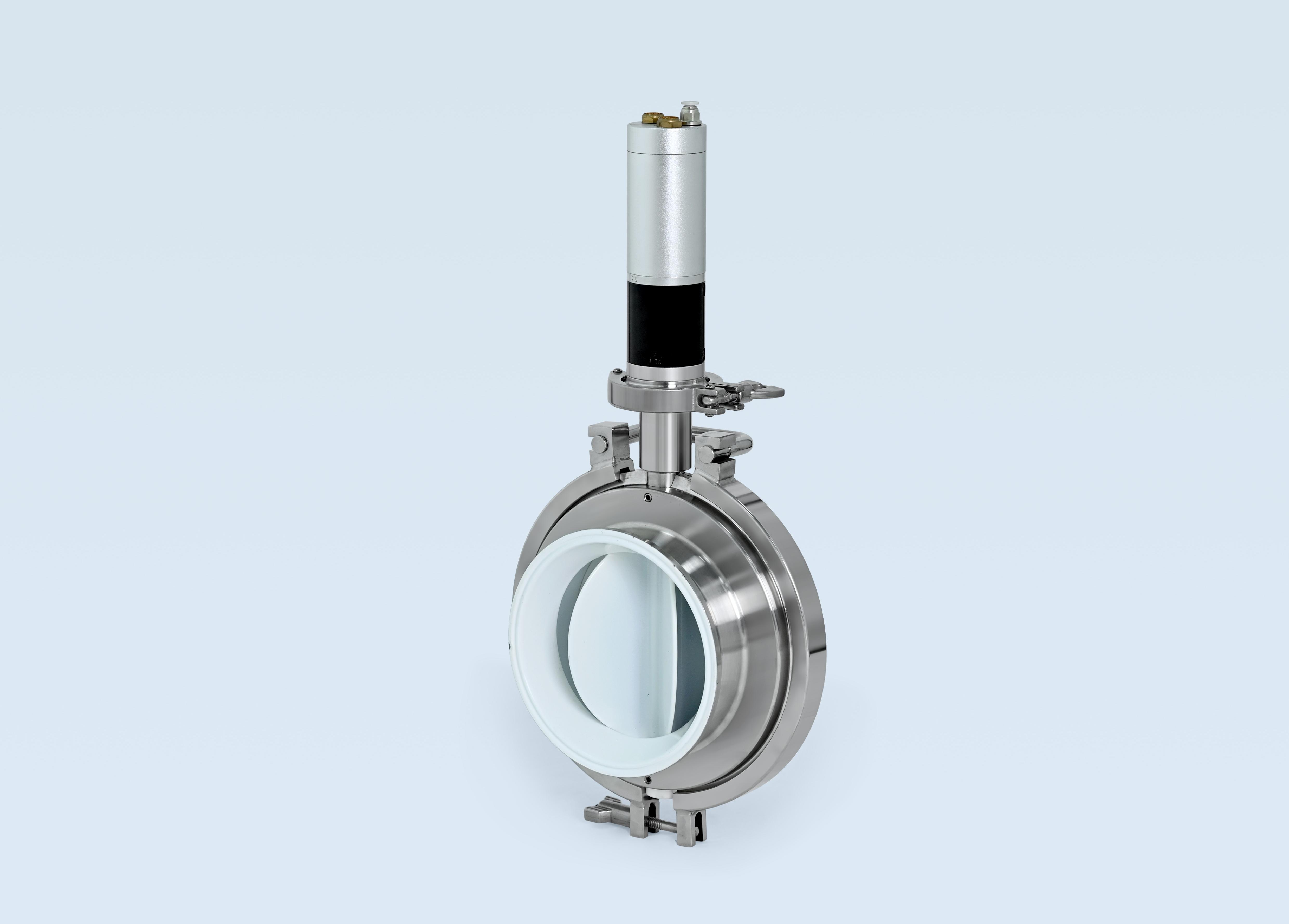
Hitting tight tolerances in cavities isn't just about picking a fine end mill—it's about controlling every variable that shifts during the cut. When you combine CNC turning and milling on the same setup, you eliminate the stack-up errors from re-fixturing, but the real battle is thermal growth. A deep cavity with a ±0.005 mm diameter tolerance will drift as the spindle heats up, so we often run a warm-up cycle, use temperature-controlled coolant, and leave a deliberate semi-finish allowance before the final pass. Even the toolholder's runout matters: anything over 3 microns at the gauge line gets rejected because it shows up directly as a taper in the bore.
The toolpath strategy makes or breaks the feature. For tight cavities, I avoid straight plunge milling—that's a quick way to get chatter and a bell-mouthed opening. Instead, use helical interpolation with a small step-down, then switch to a high-feed mill for the bulk removal and finish with a long-reach, reduced-shank end mill. If the cavity is deeper than 4×D, switch to a damped or carbide shank tool and drop the radial engagement to around 5–8% of the diameter. That keeps deflection under a couple of microns. On the turning side, boring bars with a fine-adjust boring head let you dial in the last few microns without a test cut.
After machining, verification shouldn't be an afterthought. We use a spindle probe to check the cavity diameter and roundness at two or three depths while the part is still clamped, then compensate the tool offset automatically if the deviation is consistent. For parts going into aerospace or medical devices, the temperature of the part and machine must match the CMM environment—otherwise you're chasing a moving target. A simple habit like recording the actual coolant temperature during each shift helps you spot drift before it becomes a rejected batch.
Hard Coating and Surface Finishing for Abrasive Duty
When components face constant sliding contact with hard particulates, the choice of coating becomes a direct lever on downtime and replacement costs. Hard chromium plating still finds use where moderate abrasion pairs with tight dimensional control, but its brittleness and micro-cracking push many operations toward thermally sprayed tungsten carbide or chrome oxide ceramics. These layers, often applied via HVOF or plasma spray, build a dense barrier that the abrasive media cannot easily gouge, yet their true performance depends as much on the finishing step as on the coating chemistry itself.
A rough, as-sprayed surface acts like a file against mating parts and accelerates particle embedment, so finishing is not cosmetic but structural. Diamond grinding followed by fine lapping or superfinishing removes the high asperities while preserving the coating's thickness where it matters. For softer abrasives such as rubber or polymer granules, a controlled 0.1–0.2 µm Ra finish prevents material pickup and lowers friction heat, whereas heavy mineral slurries often favor a slightly coarser crosshatch to retain a boundary lubricant film without exposing substrate.
Success lies in the interplay between coating hardness, residual stress, and the final surface texture. A well-finished chrome carbide overlay on a pump impeller can outlast bare stainless steel by a factor of eight, but if the finish is skipped or rushed, premature spalling negates that gain. The practical approach is to specify a layered system: a tough bond coat for adhesion, a thick wear layer for abrasion resistance, and a final polish tailored to the particle size and flow regime of the process.
Assembly Bay Rituals: Bearings, Seals, and Runout
Every experienced builder knows the corner of the shop where bearing installs happen isn’t just a workstation—it’s a place with its own small customs. The freezer gets raided for bearing races, the induction heater sits on a frayed extension cord, and a dead-blow hammer hangs within reach not for force, but for persuasion. Before anything goes together, the housing bore gets a wipe with a lint-free rag and a light coat of the same oil the bearing will live in. No brake cleaner, no compressed air blasting through a sealed bearing; that’s how you turn a quiet roller into a growler. Seals get the same respect: the lip is never dry, the spring stays seated, and the outer edge goes in square with a proper driver, not a socket that only touches the inner race.
Runout is where ritual turns into measurement. After the hub or shaft is torqued, a dial indicator gets mounted with the magnetic base stuck to something solid, and the needle tells you whether the stack is true or just tight. Reading a few tenths of a thousandth may sound fussy, but it catches a cocked bearing or a seal bottoming out before the machine spins up. The best builders don’t rely on feel alone; they record the high spot, mark it with a paint pen, and decide if it’s acceptable for the job. If the runout is out, the whole stack comes apart and the ritual starts again—wipe, inspect, align, press. That patience is what separates a quiet-running assembly from one that chews its own seals in a week.
The Test Bench Gauntlet: Pressure, Vacuum, and Leak Checks
A proper test bench doesn't just measure one condition—it pushes a component through a series of pressure and vacuum cycles that reveal weak seals, porous castings, or hairline cracks before they cause field failures. Rather than relying on a single pass/fail snapshot, the gauntlet approach alternates between positive pressure holds, deep vacuum pulls, and timed leak-down checks. This sequencing exposes failures that only appear after thermal or mechanical stress has had a chance to work on a suspect joint.
The leak check itself is often the most telling stage. A slow decay in pressure or an inability to reach a target vacuum usually points to more than just a bad gasket—it can indicate threading issues, warped mating surfaces, or contamination trapped in a fitting. Reading the rate of change, not just the final value, separates an experienced bench operator from someone simply following a checklist. Small fluctuations that get dismissed as noise often repeat under identical conditions, making them the earliest warning sign of a margin that will degrade over time.
Final Inspection and the Paper Trail Behind Each Valve
Before any valve leaves the floor, it gets pulled from the line and put through a final round of checks that goes beyond the usual pressure and seat tests. We look at machining marks under a bright light, verify torque on the packing bolts, and run the actuator through a full cycle while watching for even the slightest hitch in the stroke. Each of these observations is logged by hand on a traveler that follows the valve from the first forging to the crate.
That paperwork trail is not just a stack of sign-offs. It includes material heat numbers matched against the mill certificates, the exact serial numbers of the trim parts installed, and any rework notes from earlier stations. If a seat had to be lapped twice to get the leak rate down, that detail stays in the file. Buyers can trace every decision made on their specific unit months after delivery.
At the end, the inspector signs and dates the final record only after the hydrostatic test chart, the paint thickness readings, and the dimensional report are all clipped together. Nothing ships on a verbal okay. That combination of a hands-on final look and a complete, traceable document set is what keeps a valve from becoming an anonymous component in a larger system.
FAQ
Typically 304 or 316 stainless steel for corrosion resistance, but hardened tool steels or nickel alloys appear when handling abrasive or high-temperature powders. Cast iron still gets used for less demanding applications because it machines well and costs less.
We rely on multi-axis CNC machining centers and in-process probing. Critical diameters are held to within ±0.005 mm, and the rotor is often ground after turning to remove any residual ovality that could cause binding or leakage.
Each unit undergoes dimensional inspection on a coordinate measuring machine, a pressure decay test for seal integrity, and a manual rotation check under simulated load. For food or chemical service, we also run a surface finish verification using a profilometer to confirm Ra values meet specification.
Dedicated workstations and tooling sets are assigned to specific alloys, and swarf from each job is collected in labeled bins. Before switching materials, the machine enclosures are vacuumed and wiped down, and the cleaning is documented in the job traveler.
Many customers ask for 0.8 µm Ra or better on product-contact surfaces. That usually means a combination of fine turning, cylindrical grinding, and sometimes electropolishing for stainless steel parts. Cast surfaces are often left as-cast on non-contact exterior areas.
Beyond standard pressure testing, we check that all rotating and static components meet ATEX or NEC requirements for the specified zone. We also perform a continuity test from rotor to body to confirm there is no isolated conductive part that could build up a static charge.
Yes, in most cases. The rotor can be built up with a wear-resistant coating or replaced, and the housing bores can be re-machined and honed back to round. We then re-establish the original running clearances and repeat the same leak and dimensional checks as a new unit.
CNC turning handles the bulk of cylindrical features like rotor journals and housing bores with repeatable accuracy. Manual machining still shows up for one-off modifications, deburring complex pockets, or fitting a custom air purge channel on a prototype valve.
Conclusion
Inside a rotary valve factory, the path from raw bar stock to finished component is less a linear assembly line than a series of deliberate, unforgiving checkpoints. The first cuts slice cold-drawn alloy bars into rotor blanks, each one measured before it ever meets a CNC spindle. Once clamped, the turning and milling centers carve cavities with tolerances that leave almost no room for thermal drift—operators compensate for tool wear and temperature shifts on the fly, checking bores with air gauges rather than trusting the machine readout alone. From there, the parts move to hard coating, where tungsten carbide or chrome oxide layers are sprayed or welded onto sealing faces. Surface finishing then grinds and laps those surfaces to a mirror-like flatness, because in abrasive duty, a few microns of uneven wear can turn a rotary valve into a leak path.
Assembly is quieter but no less exacting. Bearings are pressed or thermally fitted, seals are installed with specific lubricants, and runout is checked with a dial indicator before the valve ever reaches the test bench. On the bench, the assembly faces a gauntlet of pressure, vacuum, and leak checks—helium sniffing, decay testing, and full-open/full-closed torque sweeps. Each result is logged, not as a formality, but as a living record tied to the valve's serial number. Final inspection adds dimensional audits and surface roughness samples to that paper trail, so a valve that leaves the floor carries with it the fingerprints of every hand and machine that touched it. This is not just manufacturing; it is a controlled argument that the valve will hold its seal when the process turns abrasive.
Contact Us
Contact Person: Ananda
Email: [email protected]
Tel/WhatsApp: 8619016718200
Website: https://www.wzaomi.com