

OEM Milled Parts Explained for Engineers and Buyers
2026-11-02
Ordering OEM milled parts shouldn't feel like a gamble. Yet for many engineers and buyers, it does—misread tolerances, vague DFM feedback, and quotes that swing wildly between suppliers. Ever wondered why two shops quote the same part with a 300% price difference? Or how to tell a precision partner from a pretender? BOYIKUN has spent years machining parts others call impossible, and this guide distills that shop-floor insight into advice you can actually use.
What Separates OEM Milled Parts from Off-the-Shelf Alternatives
The distinction usually becomes obvious the moment you try to fit a generic bracket where a machined OEM component used to sit. Off-the-shelf parts are designed to cover a broad range of applications, which means they carry unnecessary bulk, standardized hole patterns, and tolerances that rarely match the exact stack-up of your assembly. OEM milled parts, on the other hand, start from the actual geometry of the mating components. Every fillet, counterbore, and wall thickness is driven by the load path and clearance requirements of one specific machine, not by a catalog drawing that has to satisfy a dozen different customers.
Beyond simple fitment, the material and surface finish choices tend to tell the real story. A commodity part might be machined from whatever low-cost alloy was available that week, with a surface roughness spec that only cares about looking decent in a photo. OEM milling work usually specifies a particular grade of aluminum, stainless, or engineering plastic based on thermal expansion, corrosion exposure, and fatigue life. The toolpaths are programmed to avoid chatter on thin sections, and the deburring process is controlled so that no sharp edge remains to cut a seal or snag a wire harness. These are details you rarely notice until the cheap alternative fails prematurely.
There is also the matter of accountability. When an OEM milled part arrives, it often comes with material certifications, inspection reports, and a clear revision history that links it back to the engineering change order that prompted its design. That traceability matters when a field failure occurs and someone has to determine whether the part or the installation was at fault. Off-the-shelf alternatives may save money upfront, but they shift the burden of verification onto your own shop floor, where the time spent measuring, modifying, and second-guessing the fit quickly eats into any perceived savings.
Picking Alloys That Won't Crack Under Your Load Case
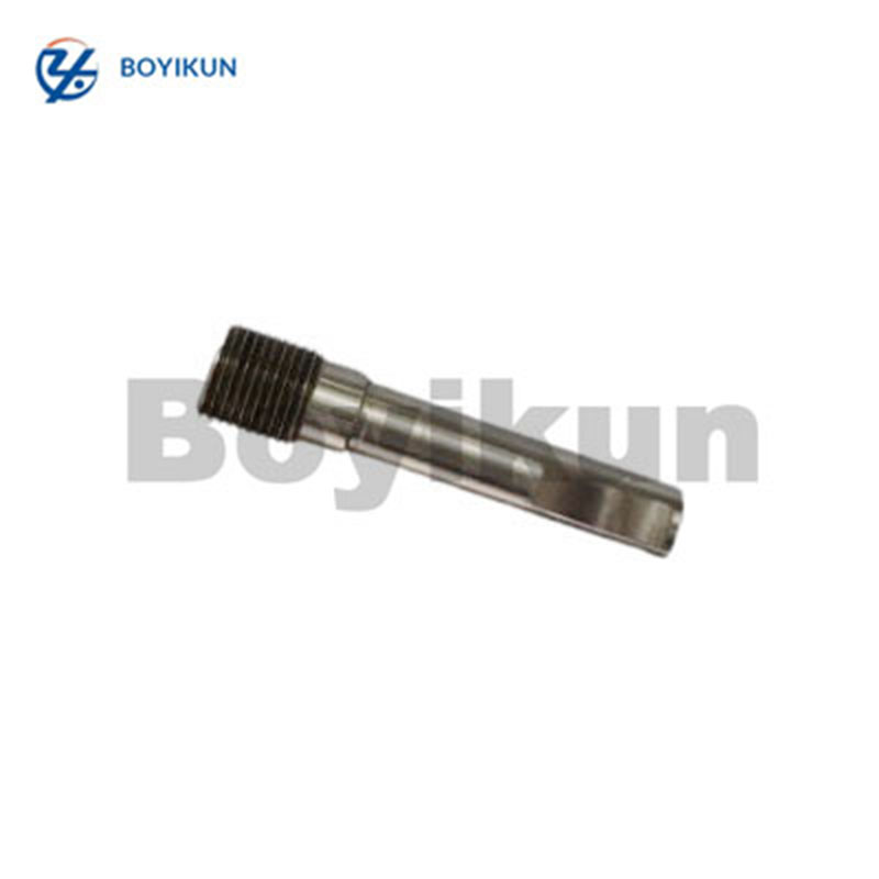
Choosing an alloy that survives a specific load case means looking beyond the headline tensile strength. A statically loaded beam might only need a high yield strength, but a shaft under cyclic bending will fail by fatigue long before it reaches yield. The first step is nailing down the actual stress state—mean stress, alternating amplitude, and how many cycles the part must endure. If the loading includes occasional overloads or impact, you also need enough ductility to deform locally instead of snapping at a stress riser.
Crack resistance often matters more than raw strength. Alloys with high fracture toughness, like 7075-T73 aluminum or Ti-6Al-4V in the annealed condition, can tolerate small flaws and stress concentrations without catastrophic failure. In contrast, some ultra-high-strength steels become so notch-sensitive that a tiny machining mark can act as a crack initiation site. Pay attention to the environment too—hydrogen from plating or corrosion can accelerate crack growth dramatically under a sustained load, turning a safe design into a time bomb.
A better selection strategy uses fatigue data or crack growth curves generated under conditions close to your application. Surface finish, residual stresses from manufacturing, and load sequence all shift the actual fatigue life. Rather than relying on a single handbook value, test the candidate alloys with realistic load spectra and inspect for microcracks. When the consequences of failure are high, lean toward alloys with a proven damage-tolerant history and design conservatively around the lower bound of their scatter band.
Tolerance Stack-Ups and Surface Finishes: Why They're Not Negotiable
When a design moves from screen to shop floor, the cumulative effect of small dimensional variations can quietly undermine an entire assembly. Tolerance stack-ups are not just a paperwork exercise; they determine whether parts mate without interference, whether seals hold pressure, and whether load paths behave as intended. A single overlooked tolerance on a bored hole or a turned shoulder can cascade into misalignment that only appears during final assembly, when rework costs are highest and delivery dates are already slipping.
Surface finish specifications often suffer from a similar under-appreciation. A mirror-smooth surface might look impressive, but if it prevents proper lubricant retention or promotes galling in a sliding contact, it is a functional liability. Conversely, a surface left too rough can become a stress riser, invite corrosion, or create noise and vibration in rotating equipment. The real skill lies in matching finish requirements to the actual duty of the part—not just defaulting to a generic callout that looks safe on a drawing.
Treating either tolerance stacks or surface finishes as negotiable after engineering release is a recipe for field failures and warranty claims. Suppliers may push back on tight tolerances or expensive finishing processes, and there is always pressure to relax requirements in the name of cost or lead time. But every loosened dimension and every skipped finishing step has a mechanical consequence. The engineers who hold the line on these specifications are not being difficult; they are protecting the function that the customer is actually paying for.
Design Choices That Reduce Machining Time Without Sacrificing Strength
One of the most effective ways to cut machining time is to design features around standard tooling. Instead of specifying a pocket with a sharp internal corner, use a radius that matches a common end mill size. This eliminates the need for a secondary EDM or tiny finishing pass, and the slight radius usually has no measurable impact on load-bearing capacity if the surrounding wall thickness is kept constant. Similarly, avoid deep, narrow slots that force long-reach tools to run at low feeds; a wider slot or a stepped shoulder can often carry the same stress without the chatter and slow material removal.
Another underused lever is symmetry. A part that can be flipped and machined identically on two sides reduces setup time and lets you use the same toolpaths in mirror. The strength advantage comes from balanced cross-sections—symmetric ribs or bosses distribute stress more evenly than an asymmetric, overly stiff one-off shape. By grouping features with the same orientation, you also limit the number of workpiece repositionings, which not only saves minutes per part but reduces the chance of tolerance stack-up that would otherwise require extra inspection or rework.
Finally, tolerance and surface finish should be treated as design variables. Calling out a 0.0005-inch flatness on an entire face when only a small sealing land actually matters doubles the grinding time for no strength benefit. A better approach is to specify a tight tolerance only on the functional zone and leave the rest at a standard machined finish. This keeps the part robust where it counts while letting the machine run at its natural speed across the rest of the geometry. Heat treatment choice also plays a role: selecting an alloy that reaches required hardness with a simple quench-and-temper instead of a long case-hardening cycle can reduce lead time without lowering yield strength.
Reading a Quote: Where OEM Milling Costs Hide
A line-item quote for CNC milling often looks straightforward, but the real cost drivers rarely appear under obvious headings. Material waste is a prime suspect—especially with complex geometries where the chip-to-part ratio can exceed 10:1. A shop might quote a low per-unit price by assuming standard stock sizes, yet your design could require oversized billets or expensive fixturing to hold thin walls. Read past the raw material line and ask how much of that block actually ends up on the floor.
Setup and programming fees are another hiding spot, frequently rolled into a single vague “engineering charge” that balloons with low volumes. One-off prototypes or small batches force the machinist to spend hours dialing in work offsets and optimizing toolpaths, but those hours get distributed unevenly across quotes. If a supplier quotes ten pieces at nearly the same price as fifty, you are paying for idle spindle time or redundant CAM work. Look for separate line items for first-article inspection, deburring, and post-machining treatments—many shops quietly absorb these until the final invoice.
Tolerances and surface finishes hide the steepest costs, though they appear as tiny symbols on a print. A ±0.005 inch feature might run in one pass on a standard mill, but tightening to ±0.0005 inches could demand a different machine class, thermal compensation, and multiple probing cycles. Anodizing or electropolishing after milling adds handling and potential rework if dimensions shift. When comparing quotes, ignore the bottom line for a minute and trace every operation from saw cut to packaging—that is where a low bid turns into a high total cost of ownership.
Verifying Quality Beyond the CMM Report
A CMM report gives you numbers, but it doesn’t tell you whether those numbers actually matter in the real world. When we verify quality beyond that report, we look at how the part behaves under load, how its surface finish feels to a fingertip, and whether the mating features slide together without persuasion. Those are the details that a coordinate list can’t capture, yet they often decide whether a customer keeps the line or sends the whole batch back.
One practical step is to pair dimensional data with functional checks. Take a machined bracket, for instance: the CMM might show every hole within tolerance, but if the bolt binds during assembly because of a slight taper or burr, the part still fails. We run a short assembly trial, check torque values, and inspect the edges under magnification. This kind of verification catches issues that exist in the gap between perfect geometry and actual usability.
Another angle is process stability over time. A single CMM report can look great while the process drifts toward the limit. By tracking tool wear, fixture clamping pressure, and ambient temperature alongside the inspection data, we can spot trends before they produce out-of-spec parts. The goal isn’t to replace the CMM report but to surround it with context, so quality becomes a story about performance rather than a page of coordinates.
FAQ
Machine specs matter less than how a shop manages setups, tooling wear, and inspection. A vendor with older 3-axis mills and a disciplined in-process check routine will often beat a newer shop that rushes through first articles. Ask about their scrap rate on similar geometries and how they handle thin-wall deflection or chatter.
Quotes that look too clean usually hide assumptions about stock size, fixturing, or deburring. Request a line-item breakdown separating material, machine time, tooling, and finishing. If a supplier can't explain why a 2-inch pocket costs more than a 3-inch one, that's a red flag.
Anything tighter than ±0.005 inches on a milled feature often forces a secondary op or slower feed rates. True position callouts below 0.010 inches on multiple holes can make a simple plate cost twice as much. Design reviews should challenge every 'just in case' tight tolerance.
Aluminum can usually hold a 32 Ra finish straight off the mill with sharp tooling, while stainless often lands around 63 Ra without extra passes. Specifying 16 Ra on stainless means adding a finishing operation and probably a price jump. Match the finish to the function—mating surfaces need smoothness, cosmetic covers can tolerate more texture.
Lead time promises only matter if the shop's queue is real. Ask for a capacity snapshot: how many spindles are idle this week, and what their current on-time delivery rate is for similar parts. A shop quoting 4 weeks with 95% on-time history beats one promising 2 weeks but shipping late half the time.
Deep pockets with square corners force EDM or broaching, internal threads near the bottom of blind holes require special taps, and unneeded flatness callouts across large surfaces invite unnecessary grinding. The biggest cost driver is usually a part that could be split into two simpler pieces but is drawn as one complex monolith.
Beyond the dimensional balloon sheet, ask for material certs, coating thickness if applicable, and photos of the fixturing setup used. A supplier that only sends a checkmarked CMM report may not have measured the features that matter most to assembly. Require them to mark which dimensions were actually verified versus assumed from programming.
It's not about complexity—it's about setups. A bracket with holes on three faces might need three separate setups on a 3-axis machine, each adding alignment error and labor. One 5-axis setup can hit all faces with better positional accuracy and often lower total cost despite a higher machine rate.
Conclusion
OEM milled parts earn their place when an off-the-shelf component would force a compromise in fit, load path, or assembly logic. The difference starts with geometry that matches your housing, not the other way around, but it quickly moves into material behavior. Alloy selection is not just about tensile strength; a 6061-T6 bracket might look fine on paper and still crack if sharp corners or thin webs concentrate stress in a way the catalog data never predicts. That is why tolerance stack-ups and surface finishes have to be treated as design inputs, not inspection afterthoughts. A ±0.05 mm hole pattern may be meaningless if the mating face has a 1.6 µm Ra finish that lets the joint slip under vibration.
The buyer's side of the conversation hinges on reading a quote properly. Low piece price often masks extra setups, special tooling, or a supplier assuming you will accept variation that your assembly cannot absorb. Smart design choices—like keeping pocket depths consistent or avoiding unnecessary 3D surfacing—cut machining time without weakening the part. But even a good quote and a clean CMM report are not enough. Ask how the shop holds process control between first article and final shipment. Look for in-process inspection records, tool wear tracking, and material certs that actually trace to the heat lot. That is where the difference between a one-time good batch and repeatable OEM supply becomes clear.
Contact Us
Contact Person: Xianchen Hu
Email: [email protected]
Tel/WhatsApp: 86-13248645200
Website: https://www.hexnb.com/