

Custom Cleanroom Engineering Solutions for Controlled Environments
2026-08-20
Precision is not a luxury in controlled environments—it's the entire foundation. Yet too many cleanroom projects still rely on off-the-shelf designs that force your process to adapt, instead of the other way around. At GENO Pharmatech, we take a different route: custom cleanroom engineering that starts with your contamination control challenges, not a catalog. From airflow modeling to modular wall systems, every square foot is engineered to fit your operation like a glove. Because when your environment isn't built around your process, you're not just compromising compliance—you're risking your product, your timeline, and your reputation. In this post, we'll break down what truly custom cleanroom engineering looks like, where standard solutions fall short, and why the right partner matters long before the first HEPA filter is installed.
When Ceiling Grids Dictate Cleanliness: Engineering Around Static Pressure
Ceiling grids do more than hold tiles—they shape airflow in ways that directly affect room cleanliness. In cleanrooms and labs, static pressure differences between adjacent spaces are the first line of defense against contamination. A grid that obstructs or redirects supply air can create subtle pressure imbalances, allowing unfiltered air to seep through gaps around light fixtures, sprinkler heads, or perimeter joints. Rather than treating the grid as a passive structural element, engineers must map how its geometry interacts with diffuser placement and return air paths.
One practical challenge is the cumulative resistance caused by dense grid layouts or recessed fixtures. Even a few Pascals of unintended pressure drop across a ceiling plane can pull air from lower-classification zones through unsealed penetrations. For example, rooms with negative pressure relative to corridors often rely on tight door sweeps and sealed ceilings. If the grid itself creates turbulence near the return plenum, the actual pressure cascade may invert locally, compromising the intended clean-to-dirty flow.
A better approach treats every grid opening as a dynamic boundary. By running computational fluid dynamics simulations that include the true grid dimensions—not just a flat ceiling assumption—engineers can identify where static pressure gradients become unstable. Simple fixes like adding gasketed tiles, rearranging return grille positions, or specifying low-resistance grid profiles often recover the design pressure differential without costly architectural changes. In critical spaces, verifying performance with multi-point pressure sensors after construction closes the loop between ceiling grid choices and actual contamination control.
Choosing Wall Systems That Handle Daily Chemical Wipe-Downs
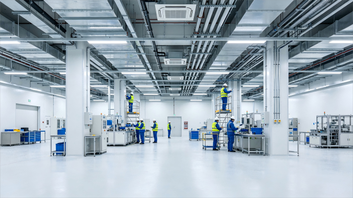
When daily chemical wipe-downs are part of the routine, wall materials need to do more than just look clean. Solid surface panels, fiberglass-reinforced plastic (FRP), and certain high-pressure laminates tend to hold up better than painted drywall or basic vinyl coverings, which can soften, stain, or peel after repeated exposure to disinfectants. Check the manufacturer's chemical resistance data against the exact products your facility uses—quaternary ammonium blends, bleach solutions, and hydrogen peroxide-based cleaners all behave differently on different resins and coatings.
Pay attention to how the system is installed, not just what it is made of. Flush joints with chemical-resistant sealant, factory-applied finishes, and seamless or heat-welded seams reduce places where cleaner can pool and cause swelling. Also avoid deep textures that trap residue. The goal is a surface that can be wiped with the same disinfectant every day without dulling, cracking, or losing its bond to the substrate.
Why Pass-Throughs Fail Quietly and How to Detail Them Right
Pass-throughs fail quietly because they rarely own their error semantics. When an upstream service returns a malformed response or times out, a simple proxy just relays the raw failure—or worse, hides it behind a generic 500. Downstream callers then waste cycles guessing whether the problem is authentication, rate limiting, or a broken payload.
Detailing them right means giving each pass-through an explicit failure contract. Normalize upstream errors into a small set of typed outcomes, add diagnostic headers or metadata (request ID, hop count, retry-after), and never convert a specific upstream error into an opaque one unless you also log the original cause. This turns silent degradation into visible, debuggable state.
Beyond error mapping, a well-detailed pass-through documents its latency tolerances and retry boundaries. If a downstream call starts failing intermittently, the pass-through should expose a circuit breaker or degraded mode indicator, not just keep forwarding empty responses. That visibility is what separates a reliable integration layer from a fragile pipe that fails silently.
Cutting Fan Energy Without Losing Your ISO Class
Many facility managers assume that reducing fan energy in a cleanroom automatically means compromising the ISO class. That fear often leads to running fans harder than necessary, wasting power and inflating operating costs. In reality, a well-planned retrofit can trim a significant share of fan energy while keeping particle counts well within limits. The key is to look beyond the fan itself and examine the entire airflow path, from the intake louvers to the terminal HEPA filters.
One practical approach is to install variable frequency drives and then tune the fan speed to match the actual cleanroom demand, rather than a fixed design maximum. By continuously monitoring differential pressure across the room and adjusting speed only when needed, you avoid the energy penalty of constant over-ventilation. Many facilities discover that their air change rates were set decades ago for a worst-case scenario that no longer exists. Rebalancing the system to deliver just enough clean air for the current process can drop fan power by 15 to 30 percent without a single excursion above the particle limit.
Another often-overlooked move is upgrading to high-efficiency fans and low-pressure-drop filters. Older centrifugal fans and standard HEPA banks can waste a surprising amount of energy overcoming internal resistance. Swapping in modern electronically commutated fans and using membrane media filters with lower initial pressure drop reduces the load on the motor. Combined with a scheduled filter replacement based on actual pressure readings rather than calendar dates, this keeps the airflow stable and the ISO classification secure. Small changes in duct sealing and eliminating unnecessary bends also add up, letting you cut fan energy while the cleanroom continues to meet its class with room to spare.
The Sequence That Turns Empty Shells Into Validated Cleanrooms
A bare concrete box doesn't become a cleanroom by installing a few fan filter units and calling it done. The transition starts with a gap analysis against the target ISO class and the specific process requirements. That means mapping pressure cascades, air change rates, filtration efficiency, and particle shedding from every surface. Only after the shell's envelope is sealed, the HVAC system balanced, and the room's recovery rate measured under dynamic conditions does the space begin to behave predictably.
Validation then moves from design intent to operational proof. Airflow visualization, particle counts at rest and in operation, filter integrity scans, and room pressurization tests build a body of evidence that the cleanroom actually holds the required conditions. The final piece is a written protocol tying each test to acceptance criteria and a change control process that preserves the validated state. That sequence—seal, stabilize, characterize, document—is what separates an empty shell from a controlled environment you can defend in an audit.
Planning for Reconfiguration Before Production Demands It
Waiting until a line struggles to adapt is the surest way to burn through both time and margin. Reconfiguration works best when it is treated as a design discipline rather than an emergency response. That means mapping likely product shifts during the initial layout phase, leaving space for tooling changes, and keeping interfaces between stations simple enough that a new fixture or robot cell can slide in without reworking adjacent flows.
The logic applies beyond machinery. Teams that plan reconfiguration early tend to standardize on modular conveyors, quick-release guarding, and control architectures where adding a sensor or divert doesn't cascade through the entire PLC program. This reduces the cost of variety and turns changeovers from a stop-the-line event into a scheduled, low-drama adjustment.
Production will eventually ask for something different. The plants that handle that moment well are rarely the ones with the fanciest equipment. They are the ones that left room to move before anyone realized they needed it.
FAQ
It covers airflow modeling, pressure cascade design, filtration selection, material compatibility, and integration of process utilities—all tailored to the cleanliness class and operational workflow.
Start with the process sensitivity and regulatory requirements, then map particle sources and occupancy to calculate the required air changes and filter coverage. A lower ISO class number means stricter limits, but over-specifying can waste energy and budget.
Ignoring pressure differentials between adjacent zones, undersizing HVAC for actual heat loads, using materials that off-gas or shed particles, and neglecting maintenance access for filter changes are frequent culprits.
Modular panels allow faster installation, easier future expansion, and better control of wall conductivity and surface finish. They also reduce on-site cutting and contamination compared to stick-built methods.
Use variable speed fans, demand-controlled filtration, high-efficiency motors, and heat recovery. Design airflow to meet particle counts without excessive turbulence, and consider night setback modes for less critical periods.
Pressure cascades create directional airflow from cleaner to less clean areas, preventing cross-contamination. Each zone's pressure setpoint and door interlocks must be tuned to actual usage patterns rather than copied from generic templates.
Often yes, by resealing penetrations, replacing ceiling grids and filters, upgrading fan filter units, adjusting HVAC controls, and adding pass-throughs or air showers. A detailed gap analysis identifies which surfaces and systems fail the target class.
As-built drawings, airflow and particle count test reports, filter certificates, material datasheets, SOPs for cleaning and monitoring, and training for operators. This package is essential for audits and future troubleshooting.
Conclusion
In controlled environments, the ceiling grid is rarely just a support structure—it becomes the first place static pressure imbalances show up. We routinely see facilities where return air paths were sized without accounting for actual filter loading, and the fix is not more fan speed but smarter zoning and damper placement. Wall systems have to survive daily chemical wipe-downs without delaminating or trapping residues, so we lean toward monolithic panels with chemical-resistant joints rather than modular systems that look clean but hide contamination in seams. Pass-throughs are another quiet failure point: gaskets compress unevenly, interlock mechanisms drift, and operators bypass them under schedule pressure. Detailing them right means specifying positive-lock doors, flush thresholds, and validation points that can be checked without opening the chamber.
Cutting fan energy does not have to cost you your ISO class. By matching filter pressure drop curves to variable-speed drives and using demand-based airflow reset, we have held Class 7 spaces at 30% lower fan power without turbulence or dead zones. The sequence from empty shell to validated cleanroom is equally deliberate: envelope first, then HVAC, then finishes, then instrumentation, with staged pressure cascade testing before any process equipment moves in. Finally, planning for reconfiguration before production demands it means laying out utility chases, ceiling grid modules, and partition anchors so that a future room split or class upgrade is a weekend change, not a shutdown. That is the difference between a cleanroom that works on day one and one that still works five years later.
Contact Us
Contact Person: Amy Yang
Email: [email protected]
Tel/WhatsApp: 008619330882686
Website: https://www.genopharmatech.com/