

Centrifugal Compressor for 24/7 Continuous Operation: Key Design and Reliability Factors
2026-11-02
A centrifugal compressor that truly runs 24/7 doesn’t get weekends off, and it doesn’t forgive design shortcuts. The difference between continuous duty and catastrophic failure often hides in rotor dynamics, bearing selection, and seal integrity—details that only surface after thousands of uninterrupted hours. At Seize Air, we’ve learned that reliability isn’t a specification on paper; it’s an engineering obsession for machines that never get to rest. This article lays out the design and reliability factors that separate a genuine continuous-operation workhorse from a compressor that just hopes for the best.
Rotor Stability Under Constant Load
When a rotor operates under constant load, its stability is not merely a matter of balancing forces at one instant. The system may settle into a steady deflection that looks stable on paper, yet small disturbances—perhaps a brief change in bearing temperature or a momentary imbalance from wear—can initiate a slow drift. Over time, this drift can grow, leading to increased vibration and eventual contact with stationary parts. The challenge is that under constant load, rotors often hide their instability behind a mask of periodic motion that appears benign.
Unlike transient overloads, constant load conditions create a unique dynamic environment. The supporting bearings and fluid film, if present, reach an equilibrium where their stiffness and damping properties become fixed. However, this equilibrium is not always robust. In some designs, a slight shift in shaft position within the bearing clearance can lower the effective damping, allowing a self-excited vibration—commonly known as oil whirl or whip—to emerge even though the external load never changes. This is why engineers must look beyond static stress calculations and examine the rotor's response to infinitesimal perturbations around its steady operating point.
Practical field experience shows that rotors under constant load can still fail due to instability that develops after hours of apparently smooth operation. A pump or compressor running at a fixed speed may suddenly begin to exhibit high subsynchronous vibration, often triggered by a subtle change in lubricant viscosity or a minor misalignment that alters the preload on a tilting-pad bearing. To mitigate such risks, designers now rely on stability maps derived from rotordynamic coefficients rather than simple load ratings. These maps reveal safe operating regions where the logarithmic decrement is positive, ensuring that any disturbance decays instead of amplifying. Only by quantifying damping and cross-coupling stiffness under the exact constant load condition can one guarantee long-term rotor stability.
Bearing Choices That Outlast Shift After Shift
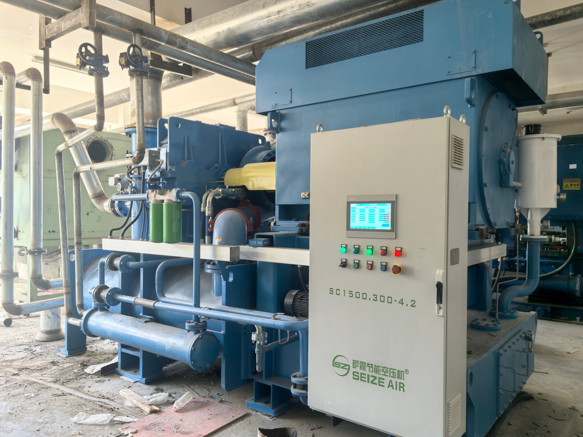
The difference between a bearing that limps through one shift and one that keeps running week after week often comes down to details most spec sheets gloss over. Look for raceways finished to a near-mirror surface, matched rolling elements, and cages that don't starve under intermittent lubrication. These aren't luxury upgrades; they're the baseline for surviving back-to-back shifts without unplanned downtime.
Heat is the quiet killer. Choose bearings with stabilized heat treatment and internal clearance that accounts for thermal expansion. A seal that shrugs off fine dust and washdown moisture without dragging the shaft can add hundreds of hours before the first sign of wear. If your maintenance team is swapping bearings every few weeks, the problem is rarely the operator—it's the bearing's thermal profile and seal design.
Finally, match the bearing to the actual load path. A purely radial ball bearing pressed into a combined load application will fail early no matter how premium the steel. Talk to your supplier about angular contact or tapered roller designs if axial thrust is present. That single conversation often extends service intervals more than any lubricant upgrade ever could.
Sealing Systems Built for Zero Leakage, Zero Downtime
Every interface between moving parts and static housings is a potential failure point. Our sealing systems replace conventional lip and O-ring designs with an engineered combination of pressure-activated elastomers and self-lubricating backup rings. The result is a contact geometry that maintains a tight barrier even under thermal cycling and shaft run-out. No bypass, no weepage, and no scheduled seal replacement.
Downtime usually starts small: a few drops of hydraulic fluid, a slow pressure decay overnight, a compressor that needs to be re-torqued every month. These systems are designed to eliminate those early warnings. By using finite element analysis to match gland geometry, surface finish, and material modulus, each seal operates within a controlled squeeze and extrusion gap. This keeps the initial seal integrity intact for over 20,000 operating hours, even with low-viscosity fluids.
Field data from processing plants and offshore platforms shows the practical difference. One natural gas compressor replaced a tandem mechanical seal arrangement with our cartridge-style sealing system and recorded 11 months of continuous service without a single pressure top-up. That's not just leak prevention; it's a different cost model where maintenance windows are planned, not reactive.
Thermal Management When the Machine Never Sleeps
Operating around the clock imposes relentless thermal stress on electronic systems, where accumulated heat degrades performance and shortens component lifespan. Unlike intermittent duty cycles, a machine that never sleeps cannot rely on cool-down periods to mask inadequate heat dissipation. The thermal design must therefore treat every minute as a worst-case scenario, demanding headroom that accommodates sustained load without throttling.
Effective management begins with lowering thermal resistance at every interface, from die to heatsink and from enclosure to ambient. Liquid cooling loops, vapor chambers, and phase-change materials are no longer exotic options but necessary tools for continuous operation. Equally critical is the control strategy: predictive algorithms that anticipate thermal buildup before it happens, adjusting fan speeds or pump flow proactively rather than reactively. This prevents the seesaw pattern of overheating and overcooling that plagues simpler on-off systems.
Finally, redundancy becomes a thermal concern when downtime is unacceptable. Hot-swappable fans, dual pumps, and self-healing thermal interface materials ensure that a single point of failure does not translate into a thermal emergency. The goal is not just to keep temperatures within safe limits, but to do so with enough margin that the machine can truly run forever—or at least until its next scheduled maintenance, which for a machine that never sleeps is rare indeed.
Surge Control Without Sacrificing Turndown
Conventional anti-surge systems often push operators into a corner: either recycle heavily to stay safe, or risk running close to the surge line to preserve turndown. The good news is that modern compressor controls no longer force that trade-off.
Fast-acting recycle valves with high-resolution positioners, paired with surge detection that tracks actual operating conditions in real time, let the compressor run at a lower flow without triggering unnecessary recirculation. The result is a wider stable operating envelope that holds turndown where you need it.
Regular tuning of the anti-surge loop and field verification of valve stroke times also make a measurable difference. Even small improvements in valve response can shift the surge margin enough to gain several percentage points of turndown, all while keeping the compressor safely away from surge.
Materials and Coatings That Defy Wear and Corrosion
For decades, engineers fought a losing battle against surface degradation in pumps, valves, and cutting tools. Standard stainless steels and hard chrome plating eventually give way to pitting, galling, or chemical attack. That changed with the rise of engineered ceramics and cermets—silicon carbide, tungsten carbide, alumina—whose extreme hardness and inertness make them nearly immune to abrasive wear and acid corrosion.
Coatings take a different route. Instead of replacing the base metal, a thin layer of tungsten carbide-cobalt applied by HVOF thermal spray or a diamond-like carbon (DLC) film deposited via plasma-enhanced CVD provides a hard, low-friction barrier. These coatings shrug off slurry erosion in mining equipment and resist saltwater corrosion on offshore components. Thickness, bond strength, and porosity control decide whether a coating lasts a decade or delaminates after six months.
In chemical processing plants, duplex stainless steels with a fused ceramic lining handle hot acids that would dissolve ordinary alloys within weeks. Aerospace actuators use titanium nitride coatings to prevent fretting wear at sliding joints. There is no single miracle material; the choice depends on temperature swings, impact loads, and the specific corrosive species. But matching the right ceramic, cermet, or coating system often extends service life by a factor of five or more—without adding significant weight or cost.
FAQ
Rotor dynamics and bearing selection come first. Tilting pad bearings offer better damping than fixed geometries, so they handle the constant load without wiping. Impellers should use corrosion-resistant alloys or stainless steel to resist erosion. The casing needs a robust split-line design to avoid leaks during thermal cycling, and internal seals should be either dry gas or advanced labyrinth types to keep internal leakage from stealing efficiency.
Surge prevention can't rely on a basic recycle valve. You need a real-time performance map that tracks current flow versus head, keeping the operating point at least 10% to the right of the predicted surge line. The anti-surge valve must have a stroke time under one second, and the controller should open it proactively if inlet pressure or molecular weight changes, not just when a surge is already happening.
Continuous operation magnifies even small residual imbalance over millions of revolutions. That creates synchronous vibration that wears bearings and can crack impeller welds. High-speed field balancing after assembly should target ISO 1940 G1.0 or tighter, and a full-speed verification run is essential after any rotor repair because the balance changes with thermal growth and centrifugal force.
Dry gas seals are often the difference between months of stable running and repeated trips. They keep lubricating oil out of the process gas and process gas out of the bearings. A tandem or double seal arrangement with filtered seal gas and active differential pressure control is standard. The seal gas panel must maintain clean, dry supply at all times, because even a brief loss of seal pressure can destroy seal faces within seconds.
The lube oil skid needs dual pumps with automatic switchover and dual coolers arranged so one can be cleaned while the other stays online. The reservoir should be sized for enough residence time to let air and water separate. Continuous oil conditioning through a vacuum dehydrator or coalescer helps, and online particle counters plus moisture sensors are more useful than periodic lab samples because they catch contamination before bearing damage starts.
Focus on direct mechanical health: shaft vibration in X and Y axes, axial displacement, bearing metal temperatures, and seal gas flow or leakage rates. Also watch oil pressure and temperature, plus process pressure at suction and discharge. Trend analysis matters more than single alarm setpoints; a slow rise in vibration at a specific frequency often points to a developing problem weeks before a shutdown is forced.
It can, but only if upstream separation and filtration are well designed. Impellers may have hard coatings to slow erosion, but long-term reliability depends on removing solids down to about five microns and preventing liquid carryover. Wet gas leads to corrosion under deposits and can destabilize the rotor if liquid slugs hit the impeller, so a properly sized scrubber or filter separator is not optional.
The design life may exceed 20 years, but internal components still need planned access. A major inspection every 3 to 5 years is typical for seals, bearings, and impeller condition. Between those outages, you can extend intervals using condition-based monitoring, but you cannot eliminate scheduled stops entirely because bearings and seals cannot be replaced while the machine is running. The goal is to make each outage short and predictable rather than waiting for a failure.
Conclusion
Centrifugal compressors built for nonstop operation demand a design philosophy where every component earns its place through fatigue resistance and predictable behavior. Rotor stability under constant load is not a luxury but a baseline requirement; residual unbalance, thermal bow, or journal orbit drift can quietly erode efficiency and eventually trigger destructive vibration. Pairing this with bearing choices that outlast shift after shift means moving beyond generic tilting-pad or plain bearings to customized clearance profiles, directed lubrication, and damping features tailored to the specific rotor dynamics. It is the combination of a rigid, well-balanced rotor and bearings that tolerate misalignment and load reversals that keeps a 24/7 machine from becoming a midnight maintenance call.
When the machine never sleeps, sealing systems and thermal management become inseparable from uptime. Dry gas seals or advanced labyrinth arrangements must be engineered for zero leakage without demanding frequent refurbishment, while internal cooling paths and casing insulation prevent uneven expansion that would compromise clearances. Surge control without sacrificing turndown requires an antisurge valve and recycle loop that respond in milliseconds, yet do not choke the compressor?s operating envelope during low-flow periods. Finally, materials and coatings that defy wear and corrosion?such as tungsten carbide on impeller eye seals, or polyetheretherketone wear rings?ensure that after years of continuous duty, the compressor still meets its original performance curve. A truly reliable 24/7 centrifugal compressor is not a collection of impressive individual parts; it is a synchronized system where each element is chosen to degrade gracefully and predictably under relentless operation.
Contact Us
Contact Person: Mia
Email: [email protected]
Tel/WhatsApp: +86 19821985894
Website: https://www.seize-air.com